The Three Most Common Types of Temperature Sensors

Temperature Sensors
Various types and styles of temperature sensors (Pyromation).

This post describes the three most popular temperature sensors, how they function, and where they are used.

THERMOCOUPLES


Thermocouples
Thermocouple illustration showing base metal designs
with various types of junctions (Pyromation).
Thermocouples are temperature sensing devices that operate on a phenomena called the Seebeck
effect. In the simplest terms, thermocouples produce a micro-voltage between two conductors - joined at each end and made of dissimilar metals - when one junction varies in temperature and the second junction (called the reference junction) is known and maintained at a constant temperature. The corresponding voltage produced at the sensing junction can be measured and directly correlated to the change in the sensing junction's temperature.

Thermocouples are popular and widely used in industrial and commercial temperate systems because they are:
  • Cost-effective.
  • Provide good accuracy.
  • Have a sufficiently linear temperature-to-signal output curve.
  • Are available in many different metal alloys for many different temperature ranges.
  • Are easily interchangeable.
Thermocouples require no external power source to work and can be used in continuous temperature measurement applications from -185 Deg. Celsius (Type T) up to 1700 Deg. Celsius (Type B).

Thermocouples are commonly found in many industrial processes. Examples are the plastics industry, primary metals, power generation, kilns, industrial boilers, HVAC, gas turbine exhaust systems and and diesel engines. And because they are affordable and easy to produce, thermocouples are also used in many consumer applications, such as residential and commercial cooking and heating equipment.

RTDs


Wirewound RTD
Wire wound RTD
(Image courtesy Wikipedia)
Resistance Temperature Detectors, referred to as RTD’s, are temperature sensing devices that determine temperature based on a relative change in resistance of the sensing element. The sensing element is a wire or etched circuit made from a metal with a well established resistance to temperature curve, most commonly platinum, nickel, or copper.  Platinum, nickel and copper are used because they produce a predictable and stable change in resistance as the temperature changes. Normally the wire is coiled around a bobbin (made of glass or ceramic), and inserted into a protective sheath. Alternatively, RTD's can also be manufactured as a thin-film, etched element with the pure metal deposited on a ceramic base, very similar to the way a printed circuit is made.

RTD’s are popular because:
  • They offer considerably higher accuracy and repeatability than thermocouples.
  • Can be used up to 600 Deg. Celsius.
  • Thin film RTD
    Thin-film RTD
    (Image courtesy of Wikipedia)
  • Can be integrated directly on the part to be monitored.
They are used where accuracy is important, such as in biomedical applications, semiconductor processing and temperature critical industrial applications. They tend to be higher priced than thermocouples because they are made of pure metals, and they do need an excitation voltage from an external source for the device to be read.


THERMISTORS


Thermistor
Another very common temperature sensing device is the thermistor. Thermistors are also a resistance measuring device similar to RTD’s. However, instead of using a pure metal as the resistance element, thermistors employ a very inexpensive polymer or ceramic resistance element. While these materials are very cost-effective, the downside is the resistance-to-temperature output curve. The change in resistance to a corresponding temperature change is very non-linear, and as such, make thermistors' use practical only within a narrow temperature range.

Thermistors are very inexpensive and have a very fast response making them very attractive in applications where a narrow sensing range exists and cost is important. Thermistors also come in two varieties, PTC, or positive temperature coefficient, and NTC, or  negative temperature coefficient. PTC's resistance increases with increasing temperature,  while NTC's resistance decreases with increasing temperature.

Thermistors are used widely in food processing in digital thermostats, and for on-board temperature monitoring of electronics and circuit boards. They are also used widely in many consumer appliances.

For more information on any temperature sensing application, contact AP Corp and discuss your requirement with one of their experienced application experts. They can be reached at (508) 351-6200 or visit them at https://a-pcorp.com.

Dynisco Online Viscosity Measurement


From the Dynisco presentation "From lab to production, providing a window into the process."

Get maximize extrusion efficiency with Dynisco Online Rheological Testing.

Dynisco online rheometers provide a "window into your process" with the ability to continuously measure critical parameters form melt flow ratio to intrinsic / relative / melt viscosity and from constant shear rate to shear sweep.

The video above introduces the Dynisco ViscoSensor, CMR IV, and FCR and presents the viewer a cost justification for their use. You can also download the presentation from the AP Corp. website here.

For more information in New England and Upstate New York, contact AP Corp. by calling (508) 351-6200 or by visiting https://a-pcorp.com.

What are Plastics Industry Feed Screws and How Are They Made?


Feed screw maintenance
Feed screw maintenance.
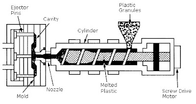
Plastics industry feed screws, or feed screw augers, are mechanisms that use rotating helical screw blades to move plastics pellets through the barrel of molding and extrusion equipment. The feed screw transports the plastic as it changes phase from solid to viscous liquid through friction, shear, and conductive heat transfer. 

A typical feed screw has three zones. Plastic pellets enters the screw feed section where the pellets are compacted and conveyed. Next is the transition (or compression) section, where the plastic is compressed, conveyed, and melted.  Finally, the liquid plastic moves to the metering section where it is precisely controlled at optimum temperature and viscosity.

For more information about feed screws, or any part of the injection molding process, contact:
508-351-6200

Injection molding
Diagram of injection molding process.


Strain Gage Sensors with Pre-attached Lead Wires


The following is from the podcast "StrainBlog" (https://www.strainblog.com) about exciting new technology for adding lead wires to strain gages. The discussion between hosts Jim and Darryl is about the development and virtues of the new Advanced Sensors Technology C4A and C5K strain gages.

AP Corp.
508-351-6200

For Strain Gage Users Who Hate to Solder - New Strain Gage Sensors with Pre-attached Leads

Strain Gage Sensors with Pre-attached Leads

The following is the transcript from the podcast "StrainBlog" (https://www.strainblog.com) about exciting new technology for adding lead wires to strain gages. The discussion between hosts Jim and Darryl is about the development and virtues of the new Advanced Sensors Technology C4A and C5K strain gages.


Jim - The topic that keeps coming up repetitively is gauges with pre-attached lead wires. I got a myriad of customers looking for a variety of different solutions. Everything from printed circuit boards, where we've got to route very fine lead wires from gauges to data acquisition systems;  civil engineering projects where they're looking for low cost, long cable lengths, sometimes two wires, sometimes three wire. There seem to be more and more demands - what are we doing to meet this variety of applications that we sort of lump into this category of pre-leaded strain gages?

Darryl - Jim, that's a fantastic question. So, we've got this new line of strain gages we call C4A's [from Micro-Measurements], and they they're available in a bunch of different sizes. We go down right now to about a 0.062" gage length, and we go up to a 0.235" gage length. We put a two conductor and a three conductor wire on it on. We can vary the length of that, and these gages are actually made using our new technology from the Advanced Sensors Group, where we can really push the limits now both on the size of the strain gage as well as the resistance. We're really excited about these. We're targeting different markets, including structural testing, as well as printed circuit board testing. There's also another one that we've recently introduced, which is a C5K version, and that's a three element rosette, a planar style that's in a 350 Ohm resistance, and with this new technology, we can make this gauge smaller, more compact than ever before, and it really makes it ideal for printed circuit board testing, where you're trying to get up close to the components that's on that board, so that you could get very accurate, localized strain gage measurements.

Jim - Now, I think I've seen one of the C5K gages that you refer to, and that's a remarkably small planar gage. If I'm correct, the footprint of that planar gage is even smaller than the smallest stacked rosette that we've ever made. Is that true?

Darryl - Yeah, you're absolutely right. So, one of the smallest stacked rosettes we've had is the 031WW as well as the G1350, and this new planar gage will actually fit within the footprint of both of those gages. The active gauge length is less than 0.020 of an inch, and we also pre-attach three conductor, 36 gauge wire to each one of those grids, so basically, you have a planar rosette with 10 feet of three conductor Teflon insulated wire that's 36 gauge in size.

Jim - Well that seems to solve a lot of problems. With stacked rosette that you have a lot of self heating issues, trying to dissipate the heat from those three layers, down to a single plane and dissipate that. With the planar rosette, all gauges air on the single plane - you don't have a proximity issue with height of sight from the neutral axis,  you don't have that heat build up, and if I remember correctly, these are actually 350 Ohm gages, not 120.

Darryl - That's absolutely right. You hit the nail on the head. These are 350 Ohm gages, so you don't have to be as concerned about self heating effects, because of the higher resistance, and also because it's a planar, and like you mentioned, there's not as much of a superposition error because that's a planar gage and not a stack one. So there should be less correction due to bending and also less concern related to excitation and self-heating of the strain gage. We're really excited about adding this to our portfolio of strain gauges that customers can use now to do this printed circuit board type testing.

Jim - And that coupled with the fine wires solves a wire routing issue, getting those leads out from between components out of the package to the data acquisition system. Sounds like a perfect solution to me.

Darryl - Yeah, we're really excited about.

For more information on strain gage sensors with pre-attached leads in New England or Upstate New York, contact AP Corp. by calling (508) 351-6200 or visit their website at https://a-pcorp.com.

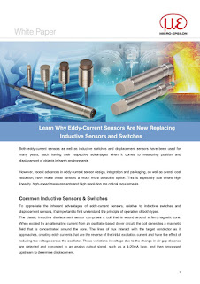
White Paper: Learn Why Eddy-Current Sensors Are Now Replacing Inductive Sensors and Switches

Eddy-Current Sensor White Paper
Recent advances in eddy-current sensor design, integration and packaging, as well as overall cost reduction, have made these sensors a much more attractive option than inductive sensors. This is especially true where high linearity, high-speed measurements and high resolution are critical requirements.

This white paper, courtesy of Micro Epsilon and AP Corp, explains why.


AP Corp
(508) 351-6200