Showing posts with label New Hampshire. Show all posts

High-Speed Color Measurement for Modern Manufacturing

Advances in High-Speed Color Measurement for Modern Manufacturing

Understanding how high-speed spectrometers measure color on manufacturing assembly lines provides a glimpse into the complex world of precision quality control and modern manufacturing techniques.

A spectrometer measures the amount of light absorbed or transmitted across different wavelengths. Color measurement involves analyzing the spectrum of light reflected off an object to determine its color.

In a typical setup on a manufacturing assembly line, a light source illuminates the product or material whose color we want to measure. This light source must remain consistent in its intensity and spectrum because any variation can influence the accuracy of the color measurement.

When the light hits the object, the object absorbs specific wavelengths of light and reflects others. The reflected light then enters the spectrometer. Inside the spectrometer, the light is dispersed, often with the help of a diffraction grating or a prism. This dispersion breaks the incoming light into its constituent colors or wavelengths, similar to a rainbow when sunlight passes through raindrops.

An array of detectors inside the spectrometer captures this dispersed light. Each detector is sensitive to a specific wavelength or a narrow range of wavelengths. By measuring the intensity of light each detector receives, the spectrometer builds a spectrum – a graphical representation of light intensity versus wavelength.

This spectrum effectively captures the color profile of the object, and a computation derives color values, typically regarding color spaces or systems like the CIELAB or RGB. These values provide a quantitative measure of the object's color compared to a standard or reference value.

In a manufacturing assembly line, the speed of this process is paramount. High-speed spectrometers capture and process data in real-time, allowing them to analyze the colors of objects as they race along the line. Suppose the color of a particular product deviates from the set standard. In that case, the system can instantly flag it for inspection or removal, ensuring that products maintain a consistent color quality throughout the production run.

The integration of high-speed spectrometers into manufacturing lines, coupled with sophisticated software, ensures that color consistency and quality meet the strict standards demanded by today's consumers and regulatory bodies. This method not only optimizes the quality of the final product but also minimizes wastage and enhances efficiency in production processes.

Micro-Epsilon stands as one of the top sensor manufacturers globally. For over 50 years, they have consistently provided reliable and high-performance solutions, especially in situations demanding high precision measurement or inspection. Their product line includes sensors for distance and displacement measurement, IR temperature measurement, and color detection, along with systems for dimensional measurement and defect detection.

The Micro-Epsilon colorCONTROL ACS7000, color measurement system, recognizes reference colors through direct comparison and distinctly identifies individual colors based on their coordinates in the color space. Equipped with a high-speed spectrometer, the colorCONTROL ACS7000 excels in applications that require online examination of colors and shades with utmost precision.

AP Corp.
(508) 351-6200
https://a-pcorp.com

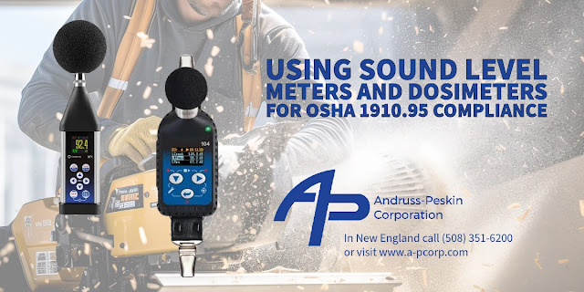
From Spot Checks to Cumulative Assessments: Understanding Noise Measurement Tools for OSHA 1910.95

From Spot Checks to Cumulative Assessments: Understanding Noise Measurement Tools for OSHA 1910.95

The Occupational Safety and Health Administration (OSHA) is an agency of the United States Department of Labor, and it is responsible for ensuring that employers provide safe and healthful working conditions for employees in the U.S. One of the ways OSHA accomplishes its mission is by setting and enforcing standards.


OSHA standard 29 CFR 1910.95 relates explicitly to occupational noise exposure. This standard protects workers from excessive noise levels that can lead to hearing loss or other health problems.


Sound level indicators (often called sound level meters or SLMs) and dosimeters are two primary instruments used to measure occupational noise levels. Both devices help employers assess noise exposure and ensure compliance with OSHA's 1910.95 standard on occupational noise exposure. 


  1. Sound Level Indicators (Sound Level Meters - SLMs):
    • Function: An SLM measures sound pressure levels in the workplace. It provides instant readings of noise levels at a specific location and time.
  • Usage:
      • SLMs spot-checks or short-term measurements in specific areas or at particular workstations where noise levels might be a concern.
      • They can identify areas in the workplace where further noise monitoring or controls may be necessary.
    • When using an SLM, it's crucial to consider the weighting scale (typically "A" weighting for human hearing) and the response time (slow or fast).
    • Data Collection: SLMs provide a snapshot of the noise level during measurement. They don't offer cumulative exposure data over time. Therefore, while SLMs can determine if a particular location is loud, they don't indicate the length of exposure to that noise level.
  1. Dosimeters:
    • Function: Dosimeters are wearable devices that measure a worker's cumulative noise exposure over time. They provide a personal noise dose reading based on the intensity and duration of sounds for individual exposure.
  • Usage:
      • Dosimeters are typically clipped to a worker's clothing and worn throughout the workday. The microphone is usually positioned near the worker's ear to assess the noise exposure accurately.
    • They benefit workers who move between different areas or tasks, resulting in varying noise exposures.
    • Data Collection: Dosimeters continuously measure and record noise levels, providing a time-weighted average (TWA) over the period worn. This data is crucial in determining worker-level exposure exceeding permissible exposure limits (PEL) set by OSHA or other regulatory bodies.


Compliance with OSHA 1910.95:


  • Employers typically start with sound level meters to identify areas or tasks with potentially hazardous noise levels.
  • Employers will use dosimeters to monitor individual exposures over the work shift if areas show elevated noise or workers' tasks involve moving between varying noise environments.
  • Suppose the noise levels exceed the action level (typically 85 dBA TWA over 8 hours). In that case, the employer must implement a hearing conservation program, which includes further monitoring, audiometric testing, training, and provision of hearing protection.


In summary, while sound level meters provide immediate spot readings of noise levels, dosimeters assess an individual's cumulative exposure over time. Both tools are essential for comprehensively evaluating workplace noise and ensuring compliance with occupational noise standards.


AP Corp.
(508) 351-6200
https://a-pcorp.com

Optimizing PCB Testing with the Latest 3-Element Stacked Rosette Strain Gauge Technology

Optimizing PCB Testing with the Latest 3-Element Stacked Rosette Strain Gauge Technology

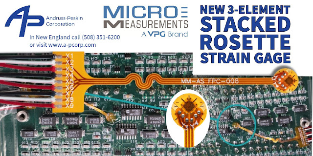
As the demand for thinner, smaller, and more densely populated PCBs increases, Micro-Measurements' new G1350A perfectly fits the bill for evaluating PCBs' stress. Thanks to the flex circuit and pre-attached lead wires, it features a compact design and significantly simplifies the installation process.

A stacked rosette strain gauge is a particular strain gauge designed to measure the typical strains along different directions at a single point. A regular strain gauge measures the deformation or strain of a material in one direction. In contrast, a rosette strain gauge, composed of multiple strain gauges, can measure strain in multiple directions. A stacked rosette strain gauge consists of several individual strain gauges stacked on each other, each oriented in a different direction to measure the strains in various directions at a single point. The stacked rosette configuration allows for a more compact design compared to a planar rosette, where the gauges are arranged next to each other.

Usage on Printed Circuit Boards (PCBs):
  • Quality Control: During the manufacturing of PCBs, there may be internal stresses generated due to various processes such as lamination, soldering, etc. These stresses may lead to the PCB's warping, bending, or even cracking. Stacked rosette strain gauges can measure these internal strains at critical points on the PCB to ensure they are within the permissible limits.
  • Design Validation: During the design phase of PCBs, engineers use finite element analysis to model and predict the strains and stresses that the PCB will be subjected to during its operation. By attaching stacked rosette strain gauges to the prototype PCBs and subjecting them to real-world operating conditions, engineers can measure the actual strains experienced by the PCB and compare them with the predicted values from the model, helping in validating the design and making any necessary modifications before mass production.
  • Failure Analysis: When a PCB fails during operation, it is essential to understand the cause of the failure to make necessary design modifications and prevent similar failures in the future. Stacked rosette strain gauges can be attached to the PCB at locations suspected of experiencing high stresses or strains. By subjecting the PCB to the operating conditions that led to the failure, engineers can measure the strains at these critical points and determine if they were the cause of the failure.
  • Thermal Expansion Measurement: PCBs often have components that generate heat during operation, which can cause thermal expansion of the material. This thermal expansion can lead to mechanical stresses and strains on the PCB and its components. Stacked rosette strain gauges can measure these strains accurately and help design PCBs that can withstand these thermal expansions without failure.

Micro-Measurements' G1350A Features:

  • Round shaped to facilitate spot installation.
  • Minimal form factor of 5.1mm diameter.
  • Readily available resistance values: 120 ohm (C4A) + 350 ohm (C4K).
  • Flex circuit connection for the most flexible and comfortable gage installation (50mm and 300mm).
  • Pre-attached lead wires: 1m or 3m length, 2 or 3 wire configuration.
  • Highly compatible with StrainSmart® software for PCB testing application features.
AP Corp.
(508) 351-6200


Load Cells: The Vital Component in Precision Weighing

Load Cells: The Vital Component in Precision Weighing

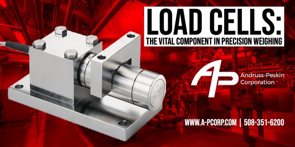
A load cell is a transducer or a sensor that converts force into an electrical signal. In industrial weighing applications, it's a critical and core component used to measure weight or force.

The most commonly used types of load cells in industrial applications are strain gauge load cells, which work on the principle of piezoresistance. When a load or force is applied to the strain gauge, it deforms or changes shape. This change in shape causes a measurable change in the electrical resistance. The change in resistance is proportional to the load applied, meaning the more significant the load, the larger the change in resistance.

This change in resistance is usually minimal, so it's converted into an electrical signal using a Wheatstone bridge configuration. The signal is then amplified and converted into a digital form by an analog-to-digital converter. This digital signal can be interpreted and displayed on a readout device, such as a digital display or a computer.

In industrial weighing applications, load cells are ubiquitous, with applications including weighing scales, industrial scales, batching scales, and load-testing machines. They can measure loads ranging from tiny (a few grams) to large (hundreds of tons).

Load cells are robust and reliable, capable of withstanding harsh industrial environments. They can handle extreme temperatures, high levels of vibration, and other challenging conditions. Additionally, they offer high precision and accuracy, which are critical in many industrial applications.

In addition to their use in weighing, load cells measure tension, compression, and shear forces, making them versatile tools in many industrial processes. They play a significant role in quality, inventory, and process control in various industries, including manufacturing, agriculture, food processing, pulp & paper, power generation, transportation, and construction.

BLH Nobel is a leading weighing and force measurement solution provider, including load cells, weighing modules, and process control equipment. The company is renowned for delivering precision, reliability, and durability, particularly in harsh industrial environments.

KIS Weigh Modules, adeptly deployed on dynamic process vessels amidst harsh, sanitation-intensive areas, have mastered the art of thriving amidst grime and grit. Their performance remains uncompromised and exceptional, even in the most challenging conditions riddled with corrosive acids, potent industrial cleaning agents, acidic vapors, and abrasive granulated powders.

Part of the remarkable performance of the BLH Nobel KIS is its ingenious cylindrical design. KIS beams can be maneuvered within the module's infrastructure, aligning precisely with the direction of the applied weight. The modules feature cylindrical, electro-polished stainless steel, forming an almost friction-free surface, allowing the module yoke to glide effortlessly during thermal expansion and contraction periods.
 

(508) 351-6200

Stress Analysis With the Use of Strain Gages

Stress Analysis With the Use of Strain Gages

When external loads are applied, stress analysis assesses the internal forces and stresses acting on a material or structure. Strain gages, widely used in this process, measure the deformation (or strain) that occurs when a material experiences stress. The following provides a detailed explanation of how to accomplish stress analysis using strain gages:


  1. Selecting strain gages: The first step involves choosing an appropriate strain gage for the specific application. Consider factors such as the type of strain (e.g., tensile, compressive, shear), the expected magnitude and direction of strain, temperature range, and material properties of the test specimen.
  2. Preparing the surface: Before attaching the strain gauge, clean and thoroughly prepare the test specimen's surface, using solvents, abrasives, or other cleaning methods to remove contaminants, ensuring proper strain gage adhesion to the surface.
  3. Installing strain gages: Bond the strain gage to the test specimen using a specialized adhesive. Align the gage carefully toward the expected stress, accurately positioning the gage grid (which contains the sensing elements) over the area of interest. Once the adhesive cures, the strain gage installation is complete.
  4. Wiring and instrumentation: Connect the strain gage to a data acquisition system using lead wires. This system usually includes a signal conditioner, which amplifies the small electrical output from the strain gage, and an analog-to-digital converter, converting the analog signal into digital data for further analysis.
  5. Calibrating: Calibrate the strain gage and data acquisition system before starting the stress analysis. Apply known loads or strains to the test specimen and record the corresponding output from the strain gage. Create a calibration curve relating the measured strain to the electrical output of the gage.
  6. Applying loads and collecting data: With the strain gage installed and calibrated, subject the test specimen to the desired external loads. As the sample deforms under load, the strain gage also deforms, causing a change in its electrical resistance. This change in resistance is proportional to the strain experienced by the material and can be measured and recorded by the data acquisition system.
  7. Analyzing data: Analyze the collected data to determine the stress experienced by the material. Typically, this involves comparing the measured strain to the material's known stress-strain relationship (e.g., elastic modulus). Depending on the complexity of the loading conditions, finite element analysis (FEA) or other computational methods may be employed to simulate the stress distribution within the specimen.
  8. Interpreting and concluding: Use the stress analysis results to evaluate the material's performance and assess the design's suitability for the intended application, including identifying potential failure points, assessing fatigue life, or optimizing the design to reduce stress concentrations.


In summary, stress analysis using strain gages requires selecting, installing, calibrating, applying external loads, collecting data, and analyzing the stress-strain data to understand the material's response to the applied loads.


(508) 351-6200

The Role of Feed Screws in The Plastics Melt Stream Process

The Role of Feed Screws in The Plastics Melt Stream Process

Feed screws, also known as extruder screws, play a crucial role in the melt stream process of the plastics industry. The melt stream process transforms raw plastic materials into a continuous, homogenized, and viscous molten mass, which can be further shaped and processed into various products like films, sheets, pipes, profiles, and more. The feed screw is an essential component of the extruder machine, the primary equipment used in the melt stream process.


The role of the feed screw in the melt stream process is explained in detail by understanding its different sections and their functions:


  1. Solid conveying (feed) zone: The feed screw consists of a helical channel or flights with a rotating shaft that runs along its length. The screw begins with a hopper where raw plastic material, usually pellets or granules, is loaded. The rotation of the screw transports the raw material forward, creating a solid conveying zone. The screw geometry in this zone efficiently moves the plastic material toward the subsequent zones.
  2. Compression (transition) zone: The depth of the screw channel decreases gradually in this zone, causing the plastic material to compress. This compression generates heat through friction, which melts the plastic along with external heating elements. At the same time, the screw design ensures proper mixing and homogenization of the plastic materials.
  3. Melting (metering) zone: This zone is characterized by a constant channel depth, where the plastic material becomes fully molten. The screw's geometry creates a uniform and consistent melt flow while providing sufficient back pressure to ensure the homogenization of the molten plastic. Additional mixing elements may be incorporated into the screw design to enhance mixing and homogenization further.
  4. Discharge (melt) zone: In this final zone, the screw conveys the molten plastic towards the extruder die, designed to shape the material into the desired product form. A screen pack and breaker plate are typically placed before the die to filter out contaminants and ensure a uniform melt flow.


Feed screws play a vital role in the overall efficiency and quality of the melt stream process. The design of the screw and its various geometries can significantly affect the processing conditions, output rate, and final product quality. Different types of feed screws are available, tailored to the specific requirements of the plastic materials and end products, such as single-screw, twin-screw, and multi-screw extruders. These screws may also be classified based on their compression ratio, screw profile, and mixing elements.


For more information about feed screws, contact AP Corp.

(508) 351-6200

AP Corp is Pleased to Announce Our Appointment as Hi-Technique’s Exclusive Authorized New England Representative

AP Corp is Pleased to Announce Our Appointment as Hi-Technique’s Exclusive Authorized New England Representative

Hi-Techniques has been an industry pioneer in High-Performance DAQ Systems for four decades. The company specializes in transient recorders, data acquisition systems, and high-resolution digital oscilloscope equipment for various applications in various industries, including Military & Aerospace, Transportation, High Voltage, and Power & Energy. Hi-Techniques is laser-focused, supplying their clients with items of the finest quality and most up-to-date technology at affordable prices.

AP Corp. is the premier manufacturers' representative company in New England and Upstate New York, providing their clients with cutting-edge measurement and control solutions. AP Corporation, established in 1959, supports customers in many industries and marketplaces through superior application support by knowledgeable and well-trained Sales Engineers.

AP Corp.
(508) 351-6200

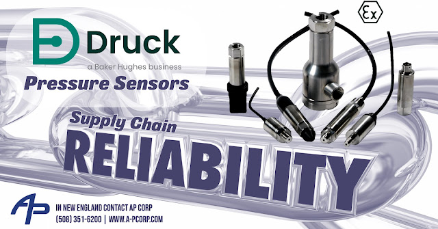
Supply Chain Reliability for Pressure Sensors

Supply Chain Reliability for Pressure Sensors

Massive disruptions to global supply networks began with the global pandemic in March 2020. The troubles swiftly expanded to worldwide manufacturing, particularly those products requiring silicon chips, semiconductors, and other digital and electronic components. Pressure sensor producers, for example, are experiencing extraordinarily long lead times on all sensors due to the supply chain issue. 

Despite global chip scarcity and the impact of supply chain restrictions, Druck has continuously expanded its production capacity to satisfy explosive demand for its pressure sensors.

The UNIK 5000 is a high-performance configurable solution to pressure measurement employing modular design and lean manufacturing techniques. Based on micro-machined silicon technology and analog circuitry, the combination enables best-in-class performance for stability, low power, and frequency response. The UNIK 5000 platform allows you to quickly build up your sensor to match your precise needs and configure a specific solution to your pressure measurement requirements. Lead times for the UNIK 5000 are still maintained at 3-4 weeks! 

For more information about Druck products in New England, contact AP Corp.
(508) 351-6200


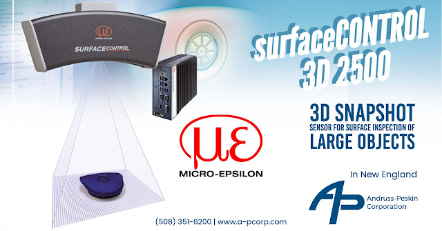
The surfaceCONTROL 3D 2500 Snapshot Sensor for Surface Inspection of Large Objects

surfaceCONTROL 3D 2500

The Micro-Epsilon surfaceCONTROL 3D sensor is ideally suited to the automated inline inspection of geometry, shapes, and surfaces on diffuse reflecting surfaces. The 3D snapshot sensors work according to the fringe projection principle, which allows direct 3D measurement of components. The sensor includes a large measuring field and a high measuring range depth with z-axis repeatability of up to 3.0 μm. Three models cover different measuring areas. 

Captured images transfer to the external SC2500 controller and are processed quickly into 3D data via the Gigabit Ethernet interfaces. The 2D/3D Gateway II supports EtherNet/IP, PROFINET, and EtherCAT connections. 3DInspect, DefMap3D, and Inspection Tools are powerful software tools that enable precise 3D measurements and surface inspection. GigE Vision compatibility also allows easy integration into third-party image processing software. The comprehensive SDK for customer software integration rounds off the software package.

surfaceCONTROL 3D Sensor Features:

  • Large objects max. 650 x 495 mm
  • High measuring range depth up to 300 mm
  • Acquisition time from 0.5 s
  • Highest precision up to 3.0 μm
  • Digital interfaces (via controller 2500): GigE Vision/GenICam
  • Digital interfaces (via 2D/3D gateway): Gigabit Ethernet (GigE Vision / GenICam) / USB2.0 / PROFINET / EtherCAT / EtherNet/IP 

surfaceCONTROL 3D Sensor Application Examples:

  • 3D inspection of geometry, shape detection and surface inspection
  • Automation, production and process monitoring as well as quality control
  • Non-contact measurement of diffuse reflective surfaces in the Stop&Go process
  • Shape, position and surface inspection
For more information about Micro-Epsilon Products in New England contact:
AP Corp.
(508) 351-6200


Understanding Load Cell Overload

Load Cell Overload

When you're talking about load cells in process weighing, what does safe and ultimate overload mean, and how strong are load cells?


The ultimate strength relates to the function as a load cell and not the mechanical strength. The mechanical strength of the load cell is even higher. 


For a load cell, there is generally three capacity limits:  


The nominal capacity of one 100%: Let's say we have a 100-pound load cell. This is the limit or capacity of the load cell. Note the load cell should not be subjected to higher forces under regular use. If the application needs to measure higher loads, then a larger load cell should be used.


The safe load usually is 200 percent of the rated capacity: Let's say with the 100-pound load cell this would be 200 pounds. If the load cell is occasionally subjected to more than 100 percent but less than 200 percent, nothing happens to it, and it will work. If repeatedly subjected to more than 100%, the load cell can be damaged due to fatigue.


The ultimate load is usually 300 percent of rated capacity or 300 pounds for a 100-pound load cell. If the load cell is occasionally subjected to a load greater than 200 percent but less than 300 percent, the load cell will be subjected to a zero shift. However, in most cases, the load cell can be recalibrated and repaired. If subjected to more than 300 percent, the bonding of the strain gauges will most likely be damaged beyond repair. The function of the load cell is damaged, and it should be scrapped. 


As a reminder, this refers to the function as a load cell and not the mechanical part. The mechanical strength of a load cell varies but is often in the range of 400 to 1 000 percent. It should also be noted that there's a fatigue limit for a load cell that generally is 133 of capacity. 


Choose Druck for Supply Chain Confidence

Choose Druck for Supply Chain Confidence

Since the pandemic, supply chain disruptions have posed a significant threat to the global economy. Factory closures and lockdowns in China and several other nations, labor shortages, strong demand for commodities, logistics network disruptions, and capacity limits have resulted in significant delivery times. Manufacturers have had to make tough choices, even relinquishing agency approvals on whole product lines.

Druck maintains regular lead times on pressure instruments and has shortened lead times from 4 weeks down to 3 to meet manufacturers' demands, particularly those facing supply chain disruptions. 

According to a poll done by the National Association of Manufacturers, 36% of companies suffer supply chain disruptions, with items arriving late or not at all. Druck works closely with its supply chain to maintain a 3-4 week delivery on the UNIK 5000 series. 

As firms look for alternative suppliers, Druck demonstrates their dependability as a domestic pressure instrument supplier, serving critical industries.

For more information about Druck products in New England, contact AP Corp.
(508) 351-6200

The Druck PACE CM3 Pressure Controller


AP Corp presents the Druck PACE CM3, a new custom-built system where the fastest pressure controller, PACE, and Druck's most accurate reference control module, CM3, are combined into one powerful, high-precision pressure measurement and control solution. PACE CM3 is part of a new generation of high precision pressure controllers from Druck. Using TERPS technology at the core, delivers an unprecedented level of performance and accuracy.

For more information about Druck products in New England, contact AP Corp.
(508) 351-6200

The Dynisco LMI5500 Series Melt Flow Indexer

Dynisco LMI5500

Of all the tests used by the plastics industry, melt flow rate testing (or melt flow index) is the most widely used. It is traditionally associated with testing polyethylene materials to determine the lot-to-lot consistency of resin lots or batches for quality control purposes. It is, however, also used for other purposes such as testing new materials, determination of material stability versus residence time within plastics processing equipment, or the assessment of regrind content within materials or moldings. It is generally a low shear rate test; however, larger weights can increase the shear rate.

A flow rate test measures a polymer’s mass flow rate (grams extruded in 10 minutes) using an orifice under specified conditions of temperature and load. Machines that determine flow rate are generally called Melt Indexers or Extrusion Plastometers. Test methods by ISO, DIN, ASTM, and others specify heat chamber and piston tip diameter such that the shear stress on the polymer is the same in all machines for a given load. In addition, material specification guidelines (by ISO, DIN, ASTM, GM, etc.) may exist, providing further constraints on how a particular material processes.

Specifically designed for the thermoplastics resin industry, the Dynisco LMI5500 Series Melt Flow Indexer has an array of features and benefits that range from ground-breaking accuracy to a unified software platform between all laboratory and online production equipment.

(508) 351-6200

Summary of Features for Ambrell's EKOHEAT® with VPA Technology™

EKOHEAT with VPA Technology

The EKOHEAT product family integrates Ambrell’s exclusive Versatile Performance Architecture (VPA). This technology breakthrough in design architecture, which includes an all-new innovative feature set, provides more versatility than any other induction heating system available today — all while delivering exceptional product performance.

Auto-Scan Capability
While an Ambrell Applications Laboratory will test your application and determine the necessary frequency, you may decide to take on additional applications later. If so, Auto-Scan will scan your application, auto-set the starting frequency and recommend RF setup parameters. If your application is outside of your EKOHEAT VPA model’s capabilities it will even offer recommendations.

High Resolution RF Output
The EKOHEAT VPA displayed RF output is the power actually delivered to the workhead. Resolution is better than 0.05% of full scale.

Universal Printed Circuit Boards
Regardless of system size and frequency, all EKOHEAT VPA products use common printed circuit boards (PCBs). A single board set addresses multiple EKOHEAT VPA systems, minimizing your inventory and eliminating model specific versions.

Industrial Ethernet Communication Compatibility
Industrial and Automation environment networking is fully supported using our chosen gateway that include CIPs (Common Industrial Protocols) such as EthernetIP, Modbus/TCP, and PROFINET protocols.

Easy-to-Use Touch Panel
The front touch panel display will allow you to easily adjust key operating parameters, change languages and read system diagnostics.

Soft Start Circuitry
AC power will not be disrupted when switching on the power to your EKOHEAT VPA power supply thanks to this feature. It eliminates the risk of tripping up other equipment when a power supply is turned on.

Universal Application Setup
The EKOHEAT VPA RF transformer accommodates worldwide voltages and provides the same output voltage. An application conducted in Europe uses the same application setup in the United States.

Two Remote Inputs
Added versatility is provided using a second remote input. Additional process variables, such as temperature can be measured, displayed, recorded and played back with the associated generator parameters.

Application Record and Playback
This feature enables you to record your heat cycle – for up to five weeks – and play it back. The benefit is that you can optimize your application and run it in the most efficient manner.

Ability to Add Power
All EKOHEAT VPA systems have the ability to work together. If you install a 250 kW system and realize later that you need 375 kW, just add a 125 kW system and they will work together seamlessly to deliver 375 KW.

RoHs Compliant
EKOHEAT VPA systems are RoHs compliant, meaning they are free of hazardous materials.

For more information about Ambrell products in New England, contact AP Corp. Call (508) 351-6200 or visit https://a-pcorp.com.

Cost Effective, Speedy Force Calibration System from BLH Nobel


A BLH Nobel customer's manufacturing process included multiple critical tanks that required regular weight calibration. The largest, a reactor, weighs 60 tons. Traditionally, they calibrated the vessels by filling them with water, a laborious and expensive process. It took a week for each tank.  Aside from filling the tanks, each must be emptied and rinsed. Finally, calibration required thorough drying before resuming production. 

BLH Nobel developed a method to elevate the vessels and read the weight change at various stages of the process. This video demonstrates that method.

BLH Nobel's solution allows the calibration of a weighing vessel, silo, or tank in a fraction of the time compared to using flowmeter or weighbridge calibration. BLH Nobel jacks the tank using hydraulics instead of loading with weights or flowmeter. Typically they measure the result in several points and verify the weighing result. BLH Nobel's method is often carried out without modifying the existing frame or structure, as most already have a suitable jacking point at each load cell.

For more information about this weighing calibration process or any BLH Nobel products in New England, contact AP Corp. Call (508) 351-6200 or visit https://a-pcorp.com.

The Micro-Measurments Model 700B Next Generation Welder

Micro-Measurments Model 700B

The Micro-Measurements Model 700B Welder is the next generation of the Model 700 Welder, which has been used for decades to install tens of thousands of strain gages worldwide. This experience and customer input and support provide more capability and flexibility while remaining in a smaller, more portable package. 

This new welder combines a high-speed spot welding rate with the enhanced safety and portability features that you have come to expect from Micro-Measurements. It is designed for spot welding the Micro-Measurements line of CEA, LWK, LEA, LZN, and LZE weldable strain gages. In all types of adverse field conditions, the 7rugged 00B performs efficiently and dependably.

The 700B's use of commercially available Lithium-ion batteries, which are easily replaced in the field and can handle 1500 welds (@30 joules) on a single charge, is a significant improvement (equivalent to welding around 30 linear weldable gage). The lightweight unit weighs approximately 8.3 lb. (3.77 kg) and is ideal for field use, overcoming the main limitations of other portable spot welders on the market. The unit also welds small thermocouples and light-gauge metal  

The Model 700B enhances Micro-Measurements' broad portfolio of weldable gages suitable for all types of applications and environments. Encapsulated, sealed, and high-temperature versions of Micro-Measurements' CEA, LWK, LEA, LZN, and LZE product families are included. Weldable sensors can be easily installed in field applications under a wide range of weather conditions because they are spot-welded rather than adhesively bonded." 

The Model 700B's welding energy can be easily adjusted by the user from 10 to 60 Joules, with a weld rate of up to 60 welds per minute, making it one of the fastest tools of its kind. The 700B is simple to clip onto a harness or carry around remote job sites, whether working suspended under a structure or in a manufacturing plant. It is particularly well-suited for working from rope access, aerial lifts, or in a laboratory setting. ​

For more information in New England, contact AP Corp. Call (508) 351-6200 or visit https://a-pcorp.com.

The Druck DPI705E Series Handheld Pressure Indicators


The Druck DPI 705E Series of handheld pressure and optional temperature indicators combine tough and rugged design with accurate and reliable measurements.

Compact and robust, the DPI 705E Series is designed for single handed operation and provides many essential features required for routine maintenance and system troubleshooting.

DPI705E Series Handheld Pressure Indicator Features

  • 48 pressure ranges from ±25 mbar to 1,400 bar (±1.69 psi to 20,000 psi / 2.5 KPa to 140 MPa)
  • Total 1 year uncertainty down to 0.05% full scale (FS) over temperature range of -10°C to +50°C
  • Integral calibration record with calibration due count-down display
  • Rugged, handheld design with backlit high-contrast display
  • Leak test, tare, maximum/minimum and filter
  • Hazardous Area (Intrinsically safe) version available
  • Optional remote plug and play pressure and Resistance Temperature Detector (RTD) sensors
  • Optional pneumatic and hydraulic hand pumps

For more information in New England, contact AP Corp. Call (508) 351-6200 or visit https://a-pcorp.com.

White Paper: Introduction to Fiber Optic Sensing

Introduction to Fiber Optic Sensing

Fiber optic sensing is becoming increasingly common in various industries, including manufacturing, medical, aerospace, automotive, civil, and energy. There are dozens of different types of technology on the market, each with its own set of capabilities. Because of the variety of technologies, navigating the fiber optic sensing landscape can be difficult.

This white paper, courtesy of Sensuron, intends to provide a framework for understanding multiple fiber optic sensing technologies and insights into market trends.

GET THE WHITE PAPER HERE

For decades, point sensing solutions such as strain gauges and thermocouples were  "good enough," but this mindset frequently stifles innovation. Today, many Sensuron clients have innovated beyond their ability to test with legacy technologies. New, robust sensing technologies, such as Sensuron fiber optic solutions that can monitor beyond the scope of point sensors, are required to enable the next generation of innovations.

For more information in New England and Upstate New York, contact AP Corp by calling (508) 351-6200 or visiting https://a-pcorp.com.