Showing posts with label Upstate New York. Show all posts

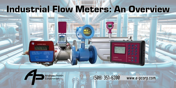
Industrial Flow Meters: An Overview

Industrial Flow Meters: An Overview

In various industrial applications, accurate flow measurement is crucial for process control, efficiency, and safety. This article briefly describes eleven common types of industrial flow meters.

1. Coriolis Flow Meters: These meters measure mass flow directly by analyzing the twisting motion of a vibrating tube caused by the Coriolis effect. They are highly accurate and can measure multiple properties such as density and temperature.

2. Magnetic Flow Meters: Also known as mag meters, these devices use Faraday's law of electromagnetic induction to measure the flow of conductive fluids. They are non-intrusive, have no moving parts, and provide high accuracy.

3. Mass Flow Meters: These meters directly measure the mass flow rate of gases or liquids. They use various technologies, such as thermal, Coriolis, or differential pressure, to determine the mass flow.

4. Ultrasonic Flow Meters: Using sound waves, these meters measure the velocity of a fluid by analyzing the time difference between ultrasonic pulses sent upstream and downstream. They are non-intrusive and suitable for clean liquids.

5. Open Channel Flow Meters: Designed for measuring flow in open channels, these meters use various methods like weirs, flumes, or ultrasonic level sensors to determine the flow rate based on the liquid level.

6. Positive Displacement Flow Meters: These meters measure flow by counting the number of times a known volume of fluid is displaced. They are highly accurate and suitable for viscous liquids and low flow rates.

7. Turbine Flow Meters: Consisting of a rotor that spins proportionally to the fluid velocity, turbine meters measure the flow rate by counting the rotations. They are compact and suitable for clean, low-viscosity fluids.

8. Variable Area Flow Meters: Also known as rotameters, these meters have a float that rises in a tapered tube proportionally to the flow rate. They are simple, cost-effective, and provide a visual indication of the flow.

9. Vortex Flow Meters: These meters rely on the von Karman effect, measuring the frequency of vortices shed by an obstruction in the flow. They are suitable for clean liquids, gases, and steam.

10. Differential Pressure Flow Meters: By measuring the pressure drop across a constriction in the flow, such as an orifice plate or Venturi tube, these meters determine the flow rate using Bernoulli's principle.

11. Thermal Flow Meters: These meters measure the mass flow of gases by analyzing the heat transfer between a heated sensor and the flowing gas. They are particularly suitable for low flow rates and high-purity gases.

Each type of flow meter has its advantages and limitations, making it essential to consider factors such as fluid properties, accuracy requirements, installation constraints, and cost when selecting the most appropriate meter for a specific application.

AP Corp.
(508) 351-6200
https://a-pcorp.com

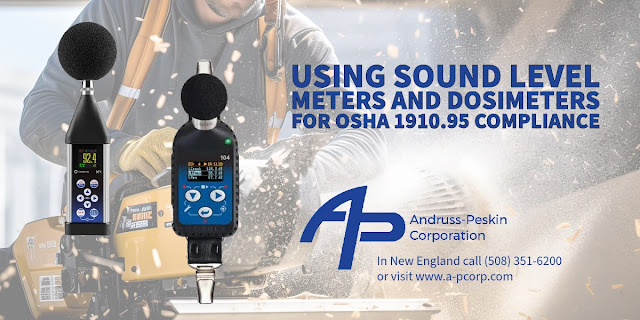
From Spot Checks to Cumulative Assessments: Understanding Noise Measurement Tools for OSHA 1910.95

From Spot Checks to Cumulative Assessments: Understanding Noise Measurement Tools for OSHA 1910.95

The Occupational Safety and Health Administration (OSHA) is an agency of the United States Department of Labor, and it is responsible for ensuring that employers provide safe and healthful working conditions for employees in the U.S. One of the ways OSHA accomplishes its mission is by setting and enforcing standards.


OSHA standard 29 CFR 1910.95 relates explicitly to occupational noise exposure. This standard protects workers from excessive noise levels that can lead to hearing loss or other health problems.


Sound level indicators (often called sound level meters or SLMs) and dosimeters are two primary instruments used to measure occupational noise levels. Both devices help employers assess noise exposure and ensure compliance with OSHA's 1910.95 standard on occupational noise exposure. 


  1. Sound Level Indicators (Sound Level Meters - SLMs):
    • Function: An SLM measures sound pressure levels in the workplace. It provides instant readings of noise levels at a specific location and time.
  • Usage:
      • SLMs spot-checks or short-term measurements in specific areas or at particular workstations where noise levels might be a concern.
      • They can identify areas in the workplace where further noise monitoring or controls may be necessary.
    • When using an SLM, it's crucial to consider the weighting scale (typically "A" weighting for human hearing) and the response time (slow or fast).
    • Data Collection: SLMs provide a snapshot of the noise level during measurement. They don't offer cumulative exposure data over time. Therefore, while SLMs can determine if a particular location is loud, they don't indicate the length of exposure to that noise level.
  1. Dosimeters:
    • Function: Dosimeters are wearable devices that measure a worker's cumulative noise exposure over time. They provide a personal noise dose reading based on the intensity and duration of sounds for individual exposure.
  • Usage:
      • Dosimeters are typically clipped to a worker's clothing and worn throughout the workday. The microphone is usually positioned near the worker's ear to assess the noise exposure accurately.
    • They benefit workers who move between different areas or tasks, resulting in varying noise exposures.
    • Data Collection: Dosimeters continuously measure and record noise levels, providing a time-weighted average (TWA) over the period worn. This data is crucial in determining worker-level exposure exceeding permissible exposure limits (PEL) set by OSHA or other regulatory bodies.


Compliance with OSHA 1910.95:


  • Employers typically start with sound level meters to identify areas or tasks with potentially hazardous noise levels.
  • Employers will use dosimeters to monitor individual exposures over the work shift if areas show elevated noise or workers' tasks involve moving between varying noise environments.
  • Suppose the noise levels exceed the action level (typically 85 dBA TWA over 8 hours). In that case, the employer must implement a hearing conservation program, which includes further monitoring, audiometric testing, training, and provision of hearing protection.


In summary, while sound level meters provide immediate spot readings of noise levels, dosimeters assess an individual's cumulative exposure over time. Both tools are essential for comprehensively evaluating workplace noise and ensuring compliance with occupational noise standards.


AP Corp.
(508) 351-6200
https://a-pcorp.com

Stress Analysis With the Use of Strain Gages

Stress Analysis With the Use of Strain Gages

When external loads are applied, stress analysis assesses the internal forces and stresses acting on a material or structure. Strain gages, widely used in this process, measure the deformation (or strain) that occurs when a material experiences stress. The following provides a detailed explanation of how to accomplish stress analysis using strain gages:


  1. Selecting strain gages: The first step involves choosing an appropriate strain gage for the specific application. Consider factors such as the type of strain (e.g., tensile, compressive, shear), the expected magnitude and direction of strain, temperature range, and material properties of the test specimen.
  2. Preparing the surface: Before attaching the strain gauge, clean and thoroughly prepare the test specimen's surface, using solvents, abrasives, or other cleaning methods to remove contaminants, ensuring proper strain gage adhesion to the surface.
  3. Installing strain gages: Bond the strain gage to the test specimen using a specialized adhesive. Align the gage carefully toward the expected stress, accurately positioning the gage grid (which contains the sensing elements) over the area of interest. Once the adhesive cures, the strain gage installation is complete.
  4. Wiring and instrumentation: Connect the strain gage to a data acquisition system using lead wires. This system usually includes a signal conditioner, which amplifies the small electrical output from the strain gage, and an analog-to-digital converter, converting the analog signal into digital data for further analysis.
  5. Calibrating: Calibrate the strain gage and data acquisition system before starting the stress analysis. Apply known loads or strains to the test specimen and record the corresponding output from the strain gage. Create a calibration curve relating the measured strain to the electrical output of the gage.
  6. Applying loads and collecting data: With the strain gage installed and calibrated, subject the test specimen to the desired external loads. As the sample deforms under load, the strain gage also deforms, causing a change in its electrical resistance. This change in resistance is proportional to the strain experienced by the material and can be measured and recorded by the data acquisition system.
  7. Analyzing data: Analyze the collected data to determine the stress experienced by the material. Typically, this involves comparing the measured strain to the material's known stress-strain relationship (e.g., elastic modulus). Depending on the complexity of the loading conditions, finite element analysis (FEA) or other computational methods may be employed to simulate the stress distribution within the specimen.
  8. Interpreting and concluding: Use the stress analysis results to evaluate the material's performance and assess the design's suitability for the intended application, including identifying potential failure points, assessing fatigue life, or optimizing the design to reduce stress concentrations.


In summary, stress analysis using strain gages requires selecting, installing, calibrating, applying external loads, collecting data, and analyzing the stress-strain data to understand the material's response to the applied loads.


(508) 351-6200

Commissioning a Dynisco Pressure Sensor Using the Dynisco 1490 Panel Indicator


Polymer manufacturing equipment such as extruders and injection molding machines are outfitted with various sensors, which allow the operators to monitor process variables, maintain safety, and avoid downtime and product output.

Dynisco manufactures precise pressure measurement and control devices that allow operators to monitor process variables, maintain safety, and avoid downtime during product output. This video will demonstrate each step of the pressure sensor commissioning process, including unpacking and wiring the sensor and setting parameter requirements for system operation.

For over 60 years, Dynisco has provided precision pressure measurement and control devices for all manner of plastic manufacturing equipment, which end-users rely on.

This video will teach you how to commission a pressure sensor with a Dynisco model 1490 indication device. The technician will offer guidance through each step of the pressure sensor commissioning process, from taking the sensor out of the box to wiring the sensor with the instrument and finally setting the parameter requirements for system operation.

This Video Covers:
  • Introduction
  • Unpacking and Examining the Pressure Sensor
  • Selecting the Cable Assembly
  • Unpacking and Wiring the Instrument
  • Connecting the Sensor Cable Assembly to the Instrument
  • Connecting the Cable Assembly to the Pressure Sensor
  • Supplying Power and Setting Parameters on the Instrument
  • Calibration of the Pressure Sensor with Instrumentation 

For more information about Dynisco products in New England and Upstate New York contact:
AP Corp.
(508) 351-6200

Sensuron - Distributed Measurement Using Fiber Optic Sensing

Distributed Measurement Using Fiber Optic Sensing

Sensuron provides intrinsic fiber optic sensing technology, using the fiber optic cable as the sensor. There are three generations of intrinsic fiber optic sensors: point fiber bragg grating (FBG) based sensors, scattering based sensors, and spatially continuous FBG based sensors. Scattering techniques use fully distributed measurements, whereas FBG techniques can use a small number of sensing points or be fully distributed, depending on how the system interprets the signal from the sensing element. 

FBGs, manufactured into the fiber's core, act like tiny mirrors. Each grating reflects a portion of the signal to the system as light travels down the fiber. The system detects and interprets changes in the returning signal to provide accurate strain and temperature measurements. The majority of FBG-based systems have a few sensing points along each fiber. While this multiplexing capability improves legacy technology, it still does not provide the sensor density required for monitoring continuous distributions. Precision, dynamic testing, and high-speed data acquisition are advantages of point FBG sensors. 

Scattering techniques do not use FBGs at all instead of relying on flaws in the fiber optic cable to obtain readings. There are three types of scattering technologies used in sensing systems today, each with its own set of capabilities. In general, distributed data and long sensing lengths benefit scattering-based fiber optic sensing systems. They are, however, limited to static operation due to low data fidelity, prolonged data acquisition rates on the order of minutes, and susceptibility to vibration. 

Sensuron employs a method that combines the advantages of point FBG sensors and scattering-based systems. Sensuron uses FBGs as the sensing element in their fiber but inscribes them continuously along its length. This process, including the signal interpretation technique, enables their platforms to collect spatially continuous data while maintaining the precision, dynamic testing, and high acquisition rates provided by FBGs. Engineers benefit from accurate measurements of full strain fields, temperature gradients, and other parameters in both static and dynamic environments. Sensuron's platforms can also measure internal and applied loads, deflection, 3D shape, and liquid level using the distributed strain data provided by the fiber.

For more information about Sensuron in New England and Upstate New York contact AP Corp. Call (508) 351-6200 or visit https://a-pcorp.com.

Summary of Features for Ambrell's EKOHEAT® with VPA Technology™

EKOHEAT with VPA Technology

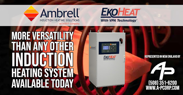
The EKOHEAT product family integrates Ambrell’s exclusive Versatile Performance Architecture (VPA). This technology breakthrough in design architecture, which includes an all-new innovative feature set, provides more versatility than any other induction heating system available today — all while delivering exceptional product performance.

Auto-Scan Capability
While an Ambrell Applications Laboratory will test your application and determine the necessary frequency, you may decide to take on additional applications later. If so, Auto-Scan will scan your application, auto-set the starting frequency and recommend RF setup parameters. If your application is outside of your EKOHEAT VPA model’s capabilities it will even offer recommendations.

High Resolution RF Output
The EKOHEAT VPA displayed RF output is the power actually delivered to the workhead. Resolution is better than 0.05% of full scale.

Universal Printed Circuit Boards
Regardless of system size and frequency, all EKOHEAT VPA products use common printed circuit boards (PCBs). A single board set addresses multiple EKOHEAT VPA systems, minimizing your inventory and eliminating model specific versions.

Industrial Ethernet Communication Compatibility
Industrial and Automation environment networking is fully supported using our chosen gateway that include CIPs (Common Industrial Protocols) such as EthernetIP, Modbus/TCP, and PROFINET protocols.

Easy-to-Use Touch Panel
The front touch panel display will allow you to easily adjust key operating parameters, change languages and read system diagnostics.

Soft Start Circuitry
AC power will not be disrupted when switching on the power to your EKOHEAT VPA power supply thanks to this feature. It eliminates the risk of tripping up other equipment when a power supply is turned on.

Universal Application Setup
The EKOHEAT VPA RF transformer accommodates worldwide voltages and provides the same output voltage. An application conducted in Europe uses the same application setup in the United States.

Two Remote Inputs
Added versatility is provided using a second remote input. Additional process variables, such as temperature can be measured, displayed, recorded and played back with the associated generator parameters.

Application Record and Playback
This feature enables you to record your heat cycle – for up to five weeks – and play it back. The benefit is that you can optimize your application and run it in the most efficient manner.

Ability to Add Power
All EKOHEAT VPA systems have the ability to work together. If you install a 250 kW system and realize later that you need 375 kW, just add a 125 kW system and they will work together seamlessly to deliver 375 KW.

RoHs Compliant
EKOHEAT VPA systems are RoHs compliant, meaning they are free of hazardous materials.

For more information about Ambrell products in New England, contact AP Corp. Call (508) 351-6200 or visit https://a-pcorp.com.

Special Offer - Up To 35% Off a Druck DPI620PC or DPI620SPC Package

35% Off a Druck DPI620PC or DPI620SPC Package

The Druck DPI 620 is a sophisticated multi-function calibrator and HART/Foundation Fieldbus communicator combined to provide a world-class pressure measurement and generation. For usage in hazardous places, ATEX and IECEx approved intrinsically safe versions are available. 

Druck is offering a special promotion. Get 35% off when you purchase a DPI620PC or DPI620SPC package.

A DPI620PC package is defined as one of the following:

  • Safe Area - PN DPI620PC-2barg, DPI620PC-7barg, DPI620PC-20barg
  • Hazardous Area - PN DPI620SPC-2barg, DPI620SPC-7barg, DPI620SPC-20barg
  • HART capability, Safe Area - PN DPI620PC- H-2barg, DPI620PC-H-7barg, DPI620PC-H-20barg
  • HART Hazardous Area - PN DPI620SPC-H-2barg, DPI620SPC-H-7barg, DPI620SPC-H-20barg

All include Druck’s latest 4Sight2 software for up to 35% off the combined list price of the individual products.

For more information in New England, contact AP Corp. Call (508) 351-6200 or visit https://a-pcorp.com.

Part Cleaning Demonstration with the Dynisco PolyClean

This video demonstrated how to clean parts, in this case pressure sensors, using the PolyClean fluidized temperature bath.

Dynisco’s PolyClean is a fluidized temperature bath that will clean parts and tooling  2 to 3 times faster and safer than traditional cleaning methods, such as ovens. Dynisco’s fluidized bath system is air¬controlled with advanced PID temperature controller for optimal thermal performance. The system uses aluminum oxide sand (heated up to 1112°F) and air to surround the part or tooling. The “sand” will gently breakdown the polymer without damaging the part or tooling.

For more information about Dynisco in New England and Upstate New York contact AP Corp. Call (508) 351-6200 or visit https://a-pcorp.com.

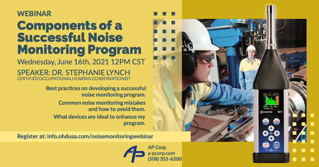
Webinar: Components of a Successful Noise Monitoring Program - June 16, 2021

Successful Noise Monitoring Program

AP Corp. is pleased to provide details for an upcoming webinar presented by OHD (Occupational Health Dynamics) and SVANTEK on implementing and operating a successful sound monitoring program.

In this 1-hour webinar, OHD's Certified Industrial Hygienist, Dr. Stephanie Lynch, will go over regulations, best practices, common downfalls, and much more when successfully building and enhancing your companies noise monitoring program. 

Stephanie Lynch is a Certified Occupational Hearing Conservationist and has over 15 years of Occupational Safety and Industrial Hygiene experience. Her doctoral dissertation research involved the collection of personal noise dosimetry and whole-body vibration measurements. Her research carries into the real world in manufacturing and military applications.

SVANTEK is the leading brand of sound and vibration meters for occupational health and safety, environmental noise, human vibration, and building vibration.

To register, visit this link (https://info.ohdusa.com/noisemonitoringwebinar). 


Dynisco Polyclean Fluidized Baths

Dynisco Polyclean Fluidized Baths

Cost-Effective, Fast, and Safe Way to Clean Various Plastic Processing Components

The Dynisco PolyClean Fluidized Temperature Baths come in three models and offer a cost-effective, fast, and safe way to clean various plastic processing components. PolyClean Fluidized Temperature Baths are applied in any polymer manufacturing or laboratory facility that needs minimal operator interaction and a low risk of harm to essential design requirements of a part during the cleaning process. 

The PolyClean 6L Fluidized Temperature Bath is ideal for cleaning small tooling from laboratory extruders or injection molding machines. 

The PolyClean 12L cleans extrusion tooling and other forms of hardware, forms parts, calibrates and tests various sensors and systems, heat treats metals and heats reactors, coils, flasks, and containers. 

The  26L PolyClean has similar functions and benefits to the PolyClean 12L, but its 26" deep basket allows it to clean larger components than the PolyClean 12L

For more information in New England and Upstate New York, contact AP Corp by calling (508) 351-6200 or visiting https://a-pcorp.com.

Now Representing Sensuron - Ultrafine Distributed and Continuous Strain & Temperature Sensing

Now Representing Sensuron

AP Corp is pleased to announce its selection as Sensuron's New England and Upstate New York Authorized Representative.

ABOUT SENSURON
Starting as an informal partnership with NASA and a formal licensing agreement in 2011, Sensuron began developing off-the-shelf fiber optic sensing systems and then designing cutting-edge fiber optic sensing platforms that allowed companies to consolidate their testing and measurement solutions. Sensuron is now a leading global provider of distributed strain and temperature sensing platforms for applications across industries and is now expanding to liquid-level and 2D deflection.

Sensuron's fiber optic sensing technology enables engineers to perform structural testing, design optimization, structural health monitoring, thermal mapping, and shape sensing with an efficient, robust, and simple-to-use tool.

AP Corp is proud to be representing Sensuron in all of New England and Upstate New York. For more information call (508) 351-6200 or visit this web page.

AP Corp.
One Tara Boulevard
Suite 200
Nashua, NH 03062
www.a-pcorp.com
508-351-6200 (office)

Combat the Hazards of Plastics Screw and Barrel Wear

Combat the Hazards of Plastics Screw and Barrel Wear

This post is abstracted from an excellent article from Plastics Technology Online
written by Jim Callari. Read the full text here.

Industrial-grade screw and barrel wear cuts throughput speeds, producing scrap before shutting down. For the first time, technology is making progress in unraveling the mystery of screw and barrel wear. 

There has been a lot of injection molding machine innovation in the past year. And now, Glycon Corp. has the technology to test wear within the plasticating device. Glycon is in the first phase of rolling this technology out in the industry. It will concentrate on extrusion and blow molding. 

With this capability, they have developed the technology to calculate the rate of wear and predict future wear. This data determines the most cost-effective time to replace these components.

Glycon has been working on measuring wear since 1986 gained their first patent as Great Lakes Feedscrews. The company expanded the invention to include measuring barrel wear and was awarded additional patents in 2006, 2007, 2008, and 2019. 

Wear and tear challenges are well documented over the years, and plastic processors know the symptoms. Many machine operators compensate by making changes to the screw speed or temperature settings. The problem is, both of these changes would ultimately result in lower efficiency and higher scrap rates. 

The new system called EMT (short for Electronic Measurement and Tracking), includes Glycon's flite-scan eddy-current sensors mounted in one or more positions within a SmartBarrel. These barrels also have SmartPorts, another innovative technology offered by Glycon. 

Measurements will be conducted routinely at the processor's plant by field technicians using a Flite-Scan sensor. Several eddy-current sensors were tried over the years. Multiple sensor manufacturers were collaborated with, but all ran into failure at high temperatures in the plasticating units. 

Micro-Epsilon, a leading manufacturer of sensors that measure displacement, distance, position, vibration, dimension and thickness, was the eventual choice because their sensors proved much more robust and provided reliable readings up to 600 F. 

The EMT system is not only to analyze the data to determine the optimum time to replace or repair worn screws or barrels to optimize productivity but also to relate the wear to:

  • Materials of screw/barrel construction.
  • Screw/barrel alignment. 
  • Polymers being processed.
  • Impact of abrasive fillers.
  • Performance related to wear, including production rates, cycle times, energy consumption, melting rates, head pressures and melt temperatures.

The Glycon EMT system's advantages are that it provides precise measurement of the wear on the OD of the feedscrew and the barrel's ID and its simplicity and cost-effectiveness. It allows maintenance personnel to plan to measure intervals and to schedule changeouts at convenient times based upon wear-rate data rather than 'running to failure' and having to run inefficiently or not at all.

For more information about the new Glycon technology in New England and Upstate New York, contact AP Corp. Call them at (508) 351-6200 or visit their website at https://a-pcorp.com.

Do You Have a Production Part Heating Challenge? Get Free Assistance from The LAB

Part Heating Lab

Ambrell's Applications Laboratory, known in the industry as THE LAB, will solve your most challenging heating applications. They will provide recommendations for precision induction heating solutions for parts of every size, shape, and material composition. 

THE LAB will apply their state-of-art testing facility, fully equipped with Ambrell induction heating systems and hundreds of proven coils. You can also interface with their engineers and see first-hand how they design prototype coils and develop innovative, practical solutions to maximize your heating process's efficiency. 

The process is easy. Just follow these three steps:

  1. Send THE LAB your parts and process requirements.
  2. Their engineers will analyze your process and heat your parts to develop the right solution for your specific application.
  3. You will receive your parts back for inspection, as well as a video of the heating process and a laboratory report with a system recommendation.

You have the option to observe testing through Ambrell's Remote Lab Service from the convenience of your office.

If you have old systems that need upgrading, why not find out if using a smaller, more efficient Ambrell induction heating system is the right solution for your process? There are measurable savings in less downtime, higher production throughput, improved energy efficiency, and more.

To learn more in New England and Upstate New York, contact AP Corp. Call them at 508-351-6200 or visit their website at https://a-pcorp.com.

Dynisco Cloud Connect™

With the new Dynisco Cloud Connect™ through Microsoft® Azure – you get a single cloud solution that aggregates all your device(s) data into one place that is secure, reliable, easy to share, with 24/7 support.

The Dynisco Cloud Connect can be used for one product or entire global production lines –whether across the street or across the globe giving you easy access to manage data across the cloud, no matter where it lives. This solution is easily expandable and is even compatible with multiple brands and equipment types, from sensors to melt flow indexers to rheometers. With Dynisco Cloud Connect, you can compare and correlate data between facilities and be able to monitor and adjust parameters in real-time, from a mobile device anywhere in the world, whether working in the field, on the production floor, or in the office. 

For more information about Dynisco products in New England and Upstate New York, contact AP Corp. Call them at (508) 351-6200 or visit their website at https://a-pcorp.com.

Which Melt Pressure Sensor Is Good for My Application?

Melt Pressure Sensor Selection

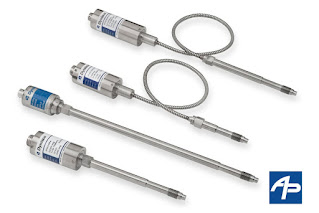
So how do I choose the right melt pressure sensor for my application? 

A sensor is defined through the following specifications:

  • Pressure Range
  • Process connection
  • Electrical output and connection
  • Capillary configuration (rigid/flexible)
Melt Pressure Sensor

There are more variables come into play, but let's focus on these four since they are the most critical.

Melt Pressure Sensor Pressure Range


The pressure inside a plastics processing machine can usually be estimated well enough to determine a sensor's good pressure range. The typical working pressure should be within 20%-80% of the sensor's pressure range to balance accuracy and lifetime.

Melt Pressure Sensor Process Connection


For threaded connections in plastics processing, a standard has developed over time, which is the ½"-20UNF thread with a conical sealing face. There might be situations where different thread sizes or a flange connection is required. There are numerous options available from manufacturers, such as Dynisco, to satisfy customer needs regarding the process connection.

Melt Pressure Sensor Electrical Output


Melt Pressure Sensor Electrical Output

A pressure sensor is an electro-mechanical device that converts a mechanical effect (pressure deflects a thin piece of metal) into an electrical signal through a strain gauge. The strain gauge changes its resistance by following the deflection of the metal piece. In the simplest case, the strain gauge signal can be used directly to feed a read-out device to display the pressure.  In order to accommodate industry-standard equipment, such as process control equipment, manufacturers like Dynisco supplies sensors with different amplified output options such as 4-20mA or 0-10V.

Melt Pressure Sensor Capillary Configuration

Melt Pressure Sensor Capillary

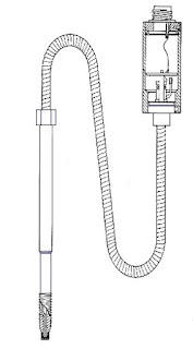
A typical pressure sensor has a liquid-filled capillary that connects the process-connection diaphragm (which is deflected by the process pressure) and the measuring diaphragm (where the strain gauge is bonded). This capillary is necessary to create a heat barrier, as the strain gauge cannot withstand the typical process temperatures at plastics processing. Also, the sensor's electronics need to be kept away from heat sources as well as possible. To find a suitable mounting location for the electronics, countless combinations of the rigid stem and flexible connection lengths are available.

Other Considerations in choosing a Melt Pressure Sensor:

  • Diaphragm materials
  • Diaphragm coatings
  • Approvals and certifications

For assistance in selecting or applying any plastics molding equipment, contact AP Corp. by calling (508) 351-6200 or visit their website at https://a-pcorp.com.

New Bench Top Series of Shaker Systems from Sentek Dynamics

Bench Top Series of Shaker Systems

The BT Series shakers from Sentek Dynamics are designed for demanding vibration test applications. Typical applications included structural analysis, calibration and testing of smaller assemblies. The BT-100 through BT-400 shakers utilize light weight rare earth magnets in lieu of traditional Alnico magnets. The use of these magnets decreases the total shaker mass to a third of similar size system, making these shakers easy to handle and portable. 

The systems range in size from 100 N (70 lbf) to 1000 N (224 lbf). Systems 400 N (99 lbf) and smaller are permanent magnet shakers and use lightweight rare earth magnets, making these systems easy to handle and portable. There are three versions of the BT Series of shakers: the BT, BT-M and BT-MTH.  

The BT Series is recommended for vibration testing of small assemblies and components. These shakers have armature diameters from 60 mm (2.36 in.) to 120 mm (4.72 in.). The BT-1000 is equipped as standard with Automatic Armature Centering (AAC) and Air-Isolation Feet (AIF).  

The BT-M and BT-MTH Series are our modal shakers lines. BT-M will use standard stingers while the BT-MTH is our through-hole version. On the 100 N and 200 N system the BT-MTH offers over double the displacement. The BT-MTH Series allow you to use piano-wire stingers. The BT-1000-M is ideal for the structural and modal analysis of high-mass structures. The addition of ZPR (electronic zero-point regulation and adjustable suspension stiffness) allows the user to pre-load the structure prior to applying a dynamic load.

The new Sentek Dynamics Bench Top and modal exciters are based upon years of practical experience. These systems all exhibit a high lateral stiffness and high force-to-weight ratio. They are specifically designed to help ensure the best possible performance with minimum setup time. 

Contact AP Corp. regarding any Sentek Dynamics product in New England and Upstate New York. Call us at (508) 351-6200 or visit our website at https://a-pcorp.com.

What is a Binocular Strain Gauge Load Cell?


Load cells, the heart of weighing systems, are mechanical devices that use strain gages to provide a measurable electrical output which is proportional to the force applied. The electrical output can be either an analog voltage or current output, or a digital on/off output.

Used for tension, compression, and or shear measurement, load cells are packaged and oriented to perform in testing equipment, electronic scales, and monitoring systems. Tension load cells are used for measuring forces that are in-line and "pull apart". Compression load cells are used to measure forces that are in-line and "push together". Shear load cells are used to measure tension or compression forces that are offset (not in-line). When selecting load cells, there are many form factors or packages to choose from to insure their physical size is compatible with space available for the application, such as inside an electronic weighing scale.

The strain gage is a resistive sensor whose resistance changes based upon the applied strain. A strain gage is attached to some structure, and when that structure is deformed (tension, compression, shear), the resistive strands in the strain gage follow the structure deformation, causing an electrical resistance change. This change in resistance is converted to units of strain or stress. 

Strain gages are used in transducers that measure force, pressure, and tension, and are often used providing stress analysis in structures such as airplanes, cars, machines, and bridges. 

When specifying strain gages one must consider the application variables, such as operating temperature, the state of the strain (including gradient, direction, magnitude, and time dependence), and the stability required by the application.

For more information about strain gages and load cells, contact AP Corp. Call them at 508-351-6200 or visit their web site at https://a-pcorp.com.

The LMI5500 Series Melt Flow Indexer from Dynisco

LMI5500
Specifically, designed for the thermoplastics resin industry the Dynisco LMI5500 Series Melt Flow Indexer has an array of features and benefits that range from ground-breaking accuracy to a unified software platform between all laboratory and online production equipment.

The LMI5500 provides a new level of simplicity of use with its simple to clean inspection plate, accessibility for sample cutting,  and improved touchscreen display.

Most notable is its own gravitational correction characteristic that takes into consideration gravity according to the units geographic location.

It is capable of delivering a wide range of data for melt flow rate, shear stress, shear rate, apparent viscosity, intrinsic viscosity, melt density, and testing conditions.


FEATURES OF THE DYNISCO LMI5500 SERIES MELT FLOW INDEXER
  • Gravitational correction
  • New Windows 10 IoT touch screen native interface
  • Built in WIFI and ethernet
  • HDMI and multiple USB ports
  • Direct digital scale USB interface for sample weighing
  • Performance meets international standards: ASTM D1238 & D3364, ISO 1133-1, BS2782, DIN 53735, JIS K7210
  • Automatic sample cutter for ease and consistency in sample cutting
  • Melt Flow Rate to Intrinsic Viscosity correlation for PET
  • Nearly unlimited program storage capability 
  • Increased access to the die for sample cutting with a strategically placed mirror to easily view the die and cutting area
  • Supports multiple languages


For more information about the Dynisco LMI5500 Series Melt Flow Indexer in New England and Upstate New York, contact AP Corporation by calling (508) 351-6200 of visit their web site at https://a-pcorp.com.

Why Plastics Industry Feed Screws are Designed the Way They Are

Feed screw selection
Download the white paper here.

The selection of the proper screw for a given injection molding or extrusion application can be critical to its success.

Screw geometry — length-to-diameter ratio, profile, channel depth, compression ratio, helix angle and a host of special design features — has everything to do with how well the screw performs in a given application.

There are documented applications where customers have improved production rates or reduced cycle times by 30 or 40% simply by switching to an improved screw design. Similarly, reject rates have been lowered from more than 4-6% to less than 1% by incorporating a custom designed mixing screw.

And experience shows that the amount of color concentrate required to achieve optimum color mix can be typically reduced from 4% (of the total blend) to 2%, just by using an optimized screw design. When considering resin and concentrate costs, payback for an optimized screw and non-return valve design can be almost immediate.

This white paper, published by Glycon Corporation, provides an in-depth look into plastics industry feed screw design.

In-Line Color Measurement for Recycled Plastic

Recycled Plastic with Color
Photo 1 - Recycled Plastic with Color
INTRODUCTION 

Color measurement is a well-accepted technology to check the quality of the color values in the production process. Usually these measurements are performed "off-line".

The delay between sampling and obtaining the results from the laboratory can be time consuming. A significant disadvantage is that only a single measurement is generated in this time period and the quality of the color during, before and after the sampling point is unknown.

With the in-line color measurements taking place directly in the melt, not only is complete documentation possible, but when color variations occur, immediate intervention can take place.

Reflection probe
Photo 2 - Reflection probe in strand pelletizer.
When recycling plastic to convert to new uniform  colored pellets many challenges can take place. Recycled plastic is much more inconsistent than virgin material. Understand-ing this inconsistency will help on your color dosing to provide a more homogeneous final product. With the proper color measurement system you can know the color values of your extrudate in real time. This allows for closing the loop on your color by changing your dosing rates to meet your specifications.

INNOVATIVE NEW TECHNOLOGY

Photo 4 - Stainless Steel NEMA4 box with touch-screen.
Technology from Equitech, a manufacturer of in-line process instrumentation, deploys a probe directly in the molten polymer. Their Reflection Polymer Melt Probe (RPMP, Photo 2) is installed on the exit (adapter) of the extruder by using ½”-20 UNF thread (typically Dynisco®). The RPMP is screwed into position in the adapter between the extruder and the die. The RPMP consists of the threaded body and optical fibers. The sapphire lens on the tip of the probe is the observation window and is very well suited to the harsh conditions in the extruder (temperature, pressure, and friction through flowing material). The self-cleaning function of the sapphire is ensured by the shear force of the material flow. Ideal installation is directly into the melt stream in the adapter.

Off-line measurements are used more effectively by downloading them to the Equitech Inline Color Spectrophotometer. This can be done manually or through OPC communications. By having the laboratory target values displayed on the Equitech system the operator can view trends of L*, a*, b* and Delta E.

This method provides complete documentation of a particular extrusion run. It also matches the known laboratory measurements giving confidence that an extrusion run has maintained specifications throughout its entirety. When color variations occur, notification can take place via digital alarms. Intervention can take place via OPC or analog signals i.e. L* feedback for closed loop color control.

EquiColor Software
Photo 3 - Trend charts of EquiColor Software
COLOR MEASUREMENT 

Illumination of the polymer through the sapphire window is achieved by 6 circumferentially-positioned glass fibers which convey the light of a xenon flash lamp. The reflection from the illuminated surface is detected by one center-positioned optical fiber. This reflected light is then interpreted by the spectrophotometer. Color values such as L*, a*, b* C*, h are calculated from this spectral curve, and displayed as trend charts, (see Photo 3).

For a continuous process monitoring, 10 to 60 seconds is recommended as the measurement interval. Intervals as fast as 1 to 2 seconds are possible. The calibration of the spectrophotometer is designed specifically for the demands of the production process. Calibration can be done without interruption of the process.

USER BENEFITS
  • Real-time information about process stability & quality
  • Impact of speed changes on the quality of the extrusion
  • Controlled color changes: start phase, end of run  
  • Avoid off-specification batches & waste production
  • Detection of dosage elevations
  • Optimized recipe formulation & process design
  • Available feedback loop for L* closed loop control via feeder
  • Comprehensive quality audit trail customer documentation
For more information, contact AP Corp. by calling (508) 351-6200 or visiting https://a-pcorp.com.

Reprinted with permission from Equitech International Corporation.